Abstract — DQ (Distributed Queue) switching is proposed as a replacement for router-based switching in the Internet. DQ utilizes a close to ideal MAC (medium access control) that enables each of the high capacity optical-fibre circuits of the underlying synchronous switching environment to deliver packet and fixed-bandwidth services to tens or hundreds of thousands of users. DQ moves packet routing to the Data Link/MAC layer resulting in two major benefits: (1) allows “seamless” integration of wireless and optical-fibre based networks, and (2) eliminates the need for routers thus eliminating congestion and simplifying the delivery of video streams. DQ can be implemented in a three-stage process. The first stage calls for the creation of Distributed Service Areas (DSAs) to which all users are connected, bypassing a significant number of routers. The second stage substitutes Q-Switches for those remaining routers that supported inter-DSA traffic during stage 1. The third and final stage calls for the adoption of the DQ MAC for all wireless applications thus once again bringing about a universal switching system, as was the case for close to a hundred years after the introduction of the telephone. The adoption of DQ switching will in all likelihood lead to the treatment of the entire Internet switching infrastructure as a public utility.
Keywords—Switch, router, networks, MAC, packet-switching, DQ, DQSA.
INTRODUCTION
Distributed Queueing (DQ), also referred to as DQSA (Distributed Queue Switch Architecture) is proposed as a switching/routing system for the Internet, one that supports both congestion-free packet and dynamically invoked fixed-bandwidth services. DQ is made feasible by the availability of a suitable Medium Access Control (MAC) and fibre optic circuits operating up to the petabit/s range. A DQ switch is distributed in that a single communication channel is efficiently shared over any distance at any bit rate by an arbitrary number of users; all control resides in the Network Interface Devices (NICs) that reside at each node, there is no central control. DQ switching utilizes broadcast/multicast to replace the mesh topology currently used by the Internet in effect moving the routing function from the Network Layer to the MAC/Data Link layer, eliminating the need for conventional routers.
The current packet switching infrastructure employs routers that in turn utilize an underlying circuit infrastructure that is an optical fibre version of the POTS (plain old telephone system) in use for almost a hundred years, i.e., it makes possible the establishment of a circuit between virtually any two points. POTS started by serving individual communities, Local Service Areas (LSA), with voice service from a central office by connecting each of the hundreds or thousands of local customers via copper wires in a star topology. The individual copper lines ofttimes had multiple customers on a single line, a “party line”.
The invention of the electron tube enabled the interconnection of LSAs on a country-wide basis. Direct-dialing eliminated manual operators and solid-state logic led to digital voice circuits and the introduction of computers. For the first time entities, albeit not human, could transmit meaningful amounts of information in microseconds, challenging a circuit-switching infrastructure designed to switch circuits that were in use for minutes. The solution was the introduction of the packet-switching router. But the existing circuit-switched infrastructure was still used to interconnect those routers, the same infrastructure that today in the main utilizes optical fibre circuits and optical switches.
Unfortunately, packet-switching is challenged by the very type of traffic that it was designed to support: a surfeit of packets leads to congestion, and in addition, routers are not amenable to providing the equivalent of fixed-bandwidth circuits, the type of circuit most suitable for the delivery of streaming video. The result is that over-engineering is necessary for effective operation.
DQ SWITCHING
DQ returns to the original POTS concept in that it utilizes the existing circuit-switched infrastructure to provision Distributed Service Areas (DSAs). A DSA utilizes a modern version of the “party line” that was in use for a hundred years, modern in the sense that the MAC employs multiplexing to serve thousands or even hundreds of thousands of customers using but a single circuit. In place of the restricted geographical area served by an LSA, a DSA can serve a community of users distributed over thousands of Km, e.g., a business with 100 branches nationwide or even a branch of the military, say all the army bases in the country.
Why refer to what appears to be an old-fashioned shared-Ethernet LAN, albeit gigantic, as a switch? The DQ MAC algorithm requires that an Ethernet frame be divided into fixed-size segments that are then transmitted by a node following a set of rules. There is the usual fragmentation loss but the Ethernet segments carry no further overhead. A switch is generally thought of a black box with multiple ports but consider that every router built directs traffic from input ports into a common buffer where a decision is made to direct a packet to a specific output port. This is what a DQ switch accomplishes excepting that the “buffer” is now distributed, a circuit that accepts all segments (the MAC ensures there are no collisions). The segments are delivered to all ports, simplifying the “switching” since each port recognizes and retrieves only its own traffic. There are still queues but they are virtual and since the physical segments are distributed across all nodes the individual node queues can control the input, thus no congestion. For transmission a node can either request the specific number of slots that will contain a specific Ethernet frame or can request a single slot on a recurring basis and thus acquire a bone fide isochronous channel.
DQ augments the “rough” granularity of optical switches with a “fine” granularity that supports the switching of 64/128/256-byte segments thus enabling packets to be transported efficiently from source to destination(s) utilizing only the PHY and MAC/Data Link layers. The need for routers is eliminated.
THREE-STAGE PLAN TO IMPLEMENT DQ
A three-stage plan is proposed to implement DQ in the core systems that support the Internet -- the terrestrial network, WiFi hotspots and the cell phone network.
These stages are:
Connect all terrestrial users to one or more DSAs depending upon geographic and/or functional interest. Inter-DSA traffic will be supported by conventional routers in this stage; intra-DSA benefits, e.g., isochronous channels and congestion-free, will not be available to inter-DSA traffic. At this time DQ technology could be used to support backhaul service for WiFi hotspots and cell towers.
Interconnect DSAs with QHubs and Q-Switches that, operating at the MAC/Data Link layer, will provide DQ benefits to inter-DSA traffic. This stage eliminate the need for conventional routers, excepting where interfacing to wireless systems.
Convert all WiFi and cell service to DQ. This step allows all hot spots, towers, etc., to be seamlessly integrated into the DQ network.
STAGE 1 - CONNECT TERRESTIAL USERS
VPNs and DSAs
A Virtual Private Network (VPN) is used by an organization to obtain the security of a private packet network yet gain the economies of using resources that are used and paid for by all, the Internet. The VPN utilizes Internet resources whose overall topology can be described as a giant mesh with nodes consisting of routers around the country. Figure 1 illustrates the implementation of several VPNs in a packet network, color-coded to show which nodes are interconnected. But plotting the traffic flow of one of the VPNs, as shown in Figure 2, and assuming a shortest-path algorithm is used, virtually all traffic flows to/from the root along branches that conform to a physical tree-and-branch topology. Note the similarity to traffic flow in a wireless network where traffic flows to/from a central node. Thus where these patterns exist in the Internet it is proposed that DQ can do a better job.
Figure 3 illustrates how a DQ-based DSA provides service that is both superior to that of a VPN and more economical. Each DSA utilizes a separate physical network rather than sharing a physical circuit as do routers but there are two reasons why this does not lead to underutilization of the physical circuit:


A DQ-based DSA can be designed for over 90% average use -- offered traffic surges exceeding 100% of capacity cause no problems -- thus leading to greater overall utilization of the physical circuits.
A DSA can itself be “virtual”, i.e., central nodes of dozens of VPNs can be co-located so as to utilize a single “fat” channel rather than multiple smaller channels.
Implementing a DSA
A DSA can also be described as a modern version of the original shared Ethernet LAN that was implemented on a coax cable using a linear or tree-and-branch topology. The difference is that the DQ MAC is close to ideal in performance, the service area is not limited, and the circuit is a standard carrier circuit, thus standard carrier circuit interface technology is utilized. All that is required when utilizing carrier circuits is the NIC at the node and the equivalent of an “or” gate at junction points. The goal of all circuit switching systems since the time of Bell has been to maintain separation between circuits, i.e., to create a separate physical circuit for each user. The goal of a DQ switch is the opposite, i.e., allow multiple users to occupy the same physical circuit - the DQ MAC ensures that only a single frame will arrive at any junction point. Thus there is a requirement for joiner/splitters for optical circuits and or/nor gates for copper circuits. There are three methods of accomplishing this modification.
It should be remembered that all of wireless communications makes use of a single high capacity “pipe” to which all users connect. Wireless is effective for synchronous channels, i.e., TV stations but utilization is poor when subject to interactive Internet traffic. The availability of an effective algorithm for sharing inbound traffic plus very high capacity of optical circuits makes it feasible to use shared switching on terrestrial circuits.
The MAC That Makes DQ Feasible
DQ switching in effect provides a “fine” granularity to complement the “coarse” granularity of the existing fibre-based synchronous infrastructure. A DQ DSA requires only a single NIC at each node, no central control is required. The NIC itself requires only interface components that are similar to those used in existing Ethernet NICs except that an ASIC/FPGA supports what can also be described as Distributed Ethernet since standard Ethernet frames are utilized. The algorithms are what make DQ unique so a short summary of the MACs follows.
The close-to-ideal MAC used by DQ is based on DQRAP, described by Xu and Campbell [1], and XDQRAP as described by Wu and Campbell [2]. DQRAP supports full utilization of a channel when the offered traffic consists of fixed-size segments, e.g., ATM cells or single readings from RFID tags. XDQRAP is a major enhancement that while still utilizing fixed-length segments supports variable length traffic, e.g., Ethernet frames, that are segmented for transmission but most importantly with no further overhead. An important feature of DQ is the ability to support both packet and fixed-bandwidth services, this feature is described by Wu and Campbell [3]. DQ supports true priorities that for instance allow preemption a jumbo Ethernet frame during transmission. See Lin and Campbell [4].
Stage 1, connecting all users to one or more DSAs can be accomplished using “off-the-shelf” hardware plus implementing the algorithms described above in VLSI/FPGA. The DSAs can be treated as an enhancement to the existing circuit-switched infrastructure, i.e., they can be treated as collectors/distributors for most of the traffic on the Internet greatly reducing the number of routers.
STAGE 2 - INTERCONNECTING DSAs
There are two phases in the interconnection of DSAs:
Cascaded Distributed Queue switching (CDQ) supports the interconnection of DSAs by using QHubs connected via a dual-bus topology. Conventional routers are still utilised to interconnect CDQ sub-networks.
Q-Switches will replace the remaining routers and provide universal interconnection at the MAC/Data Link layer.
Cascaded Distributed Queue
A single DQ-based DSA network operating at say 1 petabit/s could provide universal service in a small country. But even if technically feasible it would be preferable to utilize multiple DQ networks in the form of DSAs. The challenge was to interconnect these DSAs such that DQ features such as congestion-free service and mixed packet and fixed-bandwidth services. The solution as described by Chang and Campbell [5] was CDQ wherein a QHub serves as both a node on a DSA and the hub of an adjacent DSA. Thus a packet can “cascade” over intermediate DSAs to reach a destination.
CDQ Operation:
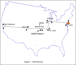
Figure 4 illustrates a CDQ network that interconnects metro-based DQ networks across the USA from New York to San Francisco. Individual metropolitan networks, possibly more than one in each area, are connected to a hub that functions both as a hub for a conventional DQ networks in that area but is also connected to adjacent hubs. We use the QNode in Kansas City to explain the operation. The Kansas City QNode acts as a central hub to the QNode at St. Louis in that St. Louis sends requests to Kansas City when it wants to transmit. It is competing with stations in Kansas City. The QNode in Kansas City sends requests to Denver when it must transmit. This is repeated across the country, duplex facilities take care of traffic in the other direction.
CDQ Performance
Packets will travel from New York to San Francisco in the network of Figure 4 without encountering congestion even when the offered traffic represents 90% of capacity. The total delay encountered by a packet in a CDQ network consists of three parts:
The access time to enter the first DQ network, i.e., request is made, station enters distributed queue, and and reaches head of queue.
The propagation delay between the origin and the destination.
The delay between arriving at each QNode and exiting that QNode.
A 10-segment CDQ network was simulated with 80%-90% total loading of Poisson point traffic that was made up of varying mixtures of through and local traffic. The local traffic consisted of both single segment traffic and traffic traveling more than one segment. The access time and propagation delay are fixed so the only variable is the QNode delay which was shown by the simulation to range from slightly over 1 slot time to under 2 slot times at each QNode. The queue length never exceeded 50 during simulations, thus buffer storage needs are minimal.
Q-Switches
QNodes have "routing" tables that are utilized very differently from those in conventional routers. When a packet reaches a QNode the destination is checked and if it is on the local network it can be assumed that the packet has reached its destination node, thus it can be discarded.
Details of the CDQ algorithm and simulation results are available from Chang and Campbell [5].
STAGE 3 - IMPLENTATION
All WiFi and cell facilities including those systems now described as being part of the Internet of Things are converted to DQ. This is not a technical challenge since it simply calls for replacing the existing MAC software by DQ software, similar to standard updates. The problem is sheer number of devices, in the billions, that have to be converted. It is preferable to delay the conversion because even though the DQ MAC will provide much improved utilization for individual wireless cells and hotspots the full benefits of DQ would not be available till the DSA backbone was in place.
ADVANTAGES OF DQ SWITCHING
Economic advantages
Utilize existing circuits, eliminating capital and maintenance costs of routers
90+% utilization of circuits.
Substantial reduction in energy requirements.
Control resides in low-cost Customer Premise Equipment (CPE) NICs.
Operational Advantages
Standard Ethernet interface thus no changes required in upper layers.
Packet transmission is not subject to congestion.
User will have the option of dynamically allocating an isochronous channel to one or more destinations, invaluable for the delivery of streaming video.
When a packet is moved to the transmission queue, the transit time will be known.
True priorities, e.g., an Ethernet jumbo frame can be preempted in mid-transmission by either the transmitting node or a distant node.
DQ can be implemented using both parallel and asymmetric circuits. These features enhance the delivery of video.
DQ broadcast/multicast capability will reduce greatly the multiple delivery of videos.
DQ Circuit as Carousel Server
A DQ 1 terabit/s circuit every two seconds would in carousel fashion make available the initial pages from approximately 1 million sites. (Google estimate of ~300,000 bytes per site).
A DQ 1 petabit/s circuit could make available hundreds of the more popular videos using Near Video-on-Demand (NVOD) that along with minimal buffering would appear as true VOD to the consumer. If the 80/20 rule applies where 80% of viewers are watching 20% of movies this would reduce bandwidth requirements for companies like NetFlix.
Many sites could make virtually all their material available via a DQ carousel server.
CONCLUSION
“The third and final stage calls for the adoption of the DQ MAC for all wireless applications, thus, once again, bringing about a universal switching system, as was the case for close to a hundred years after the introduction of the telephone. The adoption of DQ switching will in all likelihood lead to the treatment of the entire Internet switching infrastructure as a public utility.”
A three stage process is proposed that will result in DQ switching forming the basis for a universal network that supports all communications.
Stage 1 is an enhancement to the existing optical fibre infrastructure that supports both the switching of packets and the provisioning of isochronous circuits at the MAC/Data Link layer thus eliminating most routers and their attendant problems. The most significant feature of Stage 1 is the ease with which it can be implemented, current user NICs are replaced by DQ NICs (same cost) so that each user can connect to one or more DSAs. The DSAs are implemented using the existing physical circuits, excepting that routers are bypassed.
Stage 2 consists of interconnecting DSAs using QHubs and Q-Switches, eliminating the remaining routers. The operation of a QHub has been simulated [5], Q-Switch research is ongoing.
Stage 3 consists of converting all wireless systems to DQ MACs thus eliminating the distinction between Cell and WiFi networks that in turn allows the seamless interconnection of wireless facilities to the terrestrial backbone at the MAC/Data Link layer. A cell phone will then have the option of establishing either an asynchronous connection using voice packets or an isochronous connection that would enable it to receive/deliver, with greatly reduced jitter, a live video stream.
DQ switching will provide a universal homogenous switching environment that will allow the switching environment to be treated as a public utility operated by either public or private entities. The sole responsibility of these entities will be to provide the infrastructure using fibre, copper and wireless that makes available bandwidth for the transport of voice, video and data. The deliverable will be the bandwidth required by the companies, or their successors, that today provide CATV, cell, landline and cable based services. This will support the literally billions of applications that in total represents The Internet of Things.
REFERENCES
W. Xu and G. Campbell "DQRAP - A Distributed Queueing Random Access Protocol for a Broadcast Channel", presented at SIGCOMM '93, San Francisco. Computer Communication Review, Vol 23, No. 4, Oct 1993, pp. 270-278
C.T. Wu and G. Campbell, "Extended DQRAP (XDQRAP): A Cable TV Protocol Functioning as a Distributed Switch", Proceedings of 1st International Workshop on Community Networking, July 1994, San Francisco.
C. T. Wu and G. Campbell "CBR Channels on a DQRAP-based HFC Network", SPIE '95 (Photonics East), Philadelphia, PA Oct. 1995.
H.J. Lin and G. Campbell “PDQRAP - Prioritized Distributed Queueing Random Access Protocol”, Proceedings of 19th Conference on Local Computer Networks, Oct 1994, pp 82-91.
Andrew Chen-Hung Chang and G. Campbell "Cascaded Distributed Queue Switching", Unpublished.